- 您现在的位置:买卖IC网 > Sheet目录1247 > TC642DEMO (Microchip Technology)DEMO BOARD FOR TC642/46/47/48/49
�� �
�
�TC64X/TC64XB Fan Control Demo Board User’s Guide�
�2.1.2�
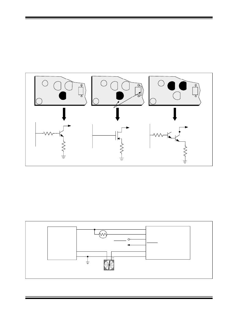
�Using� Logic� Level� MOSFETS�
�Substituting� a� logic� level� MOSFET� for� Q� 3� (such� as� a� BS170)� results� in� lower� system�
�voltage� losses� and� significantly� reduces� output� loading� on� the� TC64X� and� TC64XB�
�devices.� The� low� R� DSON� of� the� MOSFET� (1� ?� in� the� case� of� the� BS170)� enables� it� to� be�
�used� instead� of� the� Darlington� configuration� in� high-current� fan� applications.� Refer� to�
�the� Applications� section� of� the� TC64X� and� TC64XB� data� sheets� for� details.�
�Population� options� for� single� transistor� output� drivers� (using� either� MOSFET� or� bipolar�
��C� 7�
�Q� 1�
�Q� 3�
�C�
�B�
�E�
�Q� 2�
�R� 5�
�C� 7�
�Q� 1�
�Q� 3�
�D�
�G�
�S�
�Q� 2�
�R� 5�
�C� 7�
�Q� 1�
�Q� 3�
�C�
�B�
�E�
�Q� 2�
�C�
�B�
�E�
�R� 5�
�Reverse� Orientation� of�
�Q� 3� and� Jumper� R� 5�
�7�
�R� 5�
�To� Fan� (–)�
�Q� 3� (2N2222A)�
�7�
�Jumper�
�R� 5�
�To� Fan� (–)�
�Q� 3� (BS170)�
�7�
�R� 5�
�Q� 1�
�Q� 2�
�To� Fan� (–)�
�FIGURE� 2-1:�
�R� 6�
�R� 6�
�Output� Driver� Configuration� Options�
�Q� 1� ,� Q� 2� =� 2N2222A�
�R� 6�
�2.2�
�SYSTEM� CONNECTION� FOR� +5V� OPERATION�
��operating� voltage� is� +12V,� while� the� fan� control� module� operates� from� a� supply� voltage�
�of� +5V.� A� NTC� thermistor� connects� from� the� SENSOR� input� of� the� fan� control� module�
�to� V� DD� .� Fan� control� module� resistors� R� 1� and� R� 2� (See� Figure� A-2),� in� conjunction� with�
�characteristics� of� the� NTC� thermistor,� determine� the� fan� speed� versus� the� temperature�
�profile� of� the� system.�
�+5V�
�V� DD�
�Power� Supply�
�+12V�
�GND�
�NTC�
�Thermistor�
�+�
�System�
�Shutdown�
�SENSOR�
�V� AS� /V� MIN�
�FAULT�
�FAN(–)�
�GND�
�TC64X/TC64XB�
�Demo�
�Fan� Control�
�Module�
�Fan�
�FIGURE� 2-2:�
�DS21401C-page� 6�
�Typical� Wiring� Connections� to� Fan� Module� for� +12V� Fan� and� +5V� Module� Supply�
�?� 2003� Microchip� Technology� Inc.�
�发布紧急采购,3分钟左右您将得到回复。
相关PDF资料
TC642EV
KIT EVALUATION FOR TC642
TC650DEMO
DEMO BOARD FOR TC650/651 1"X1"
TC652DEMO
DEMO BOARD FOR TC652/653 1"X1.2"
TCF250-100RT-B-0.5
POLYSWITCH PTC RESET 0.1A CHIP
TCF250-100T-B-0.5
POLYSWITCH PTC RESET 0.1A CHIP
TCF250-100T-RA-B-0.5
POLYSWITCH PTC RESET 0.1A CHIP
TCF250-100T-RB-B-0.5
POLYSWITCH PTC RESET 0.1A CHIP
TCF250-120T-B-0.5
POLYSWITCH PTC RESET 0.12A CHIP
相关代理商/技术参数
TC642DEMO
制造商:Microchip Technology Inc 功能描述:Tools Development kit For Use
TC642EOA
功能描述:马达/运动/点火控制器和驱动器 w/Fault Dtct RoHS:否 制造商:STMicroelectronics 产品:Stepper Motor Controllers / Drivers 类型:2 Phase Stepper Motor Driver 工作电源电压:8 V to 45 V 电源电流:0.5 mA 工作温度:- 25 C to + 125 C 安装风格:SMD/SMT 封装 / 箱体:HTSSOP-28 封装:Tube
TC642EOA713
功能描述:马达/运动/点火控制器和驱动器 w/Fault Dtct RoHS:否 制造商:STMicroelectronics 产品:Stepper Motor Controllers / Drivers 类型:2 Phase Stepper Motor Driver 工作电源电压:8 V to 45 V 电源电流:0.5 mA 工作温度:- 25 C to + 125 C 安装风格:SMD/SMT 封装 / 箱体:HTSSOP-28 封装:Tube
TC642EPA
制造商:MICROCHIP 制造商全称:Microchip Technology 功能描述:PWM Fan Speed Controller with FanSense⑩ Technology
TC642EUA
功能描述:马达/运动/点火控制器和驱动器 w/Fault Dtct RoHS:否 制造商:STMicroelectronics 产品:Stepper Motor Controllers / Drivers 类型:2 Phase Stepper Motor Driver 工作电源电压:8 V to 45 V 电源电流:0.5 mA 工作温度:- 25 C to + 125 C 安装风格:SMD/SMT 封装 / 箱体:HTSSOP-28 封装:Tube
TC642EUA713
功能描述:马达/运动/点火控制器和驱动器 w/Fault Dtct RoHS:否 制造商:STMicroelectronics 产品:Stepper Motor Controllers / Drivers 类型:2 Phase Stepper Motor Driver 工作电源电压:8 V to 45 V 电源电流:0.5 mA 工作温度:- 25 C to + 125 C 安装风格:SMD/SMT 封装 / 箱体:HTSSOP-28 封装:Tube
TC642EV
功能描述:电源管理IC开发工具 For TC642/6/7/8/9 RoHS:否 制造商:Maxim Integrated 产品:Evaluation Kits 类型:Battery Management 工具用于评估:MAX17710GB 输入电压: 输出电压:1.8 V
TC642EV
制造商:Microchip Technology Inc 功能描述:Tools Development kit For Use